Spotlight › Breadboard XT
Breadboard XT
A circuit workbench for the IBM PC. Put resistors, LEDs, logic chips and a 555 timer on an on-screen breadboard, wire them up, press Run, and watch the circuit work on a built-in oscilloscope.
- Parts on a board
- Up to 64
- Example circuits
- 8
- Memory it needs
- 256KB
01 / What it is
What it is
A breadboard is a plastic board full of holes that people use to try out an electronic circuit without soldering it. Under each short row of holes is a metal strip, so a part pushed into one hole is connected to everything else in that row. Long strips down each side carry the power. You push the parts in, add jumper wires between rows, and connect a battery.
Breadboard XT draws that board on the screen and works out what the circuit would do. The board has 30 columns. Each column has two strips of five holes, a to e and f to j, with a gap between them where a chip sits. A pair of power rails runs along the top and another along the bottom, each split in the middle the way many real boards are.
The parts are the ones a first electronics kit has: resistors, capacitors, LEDs, switches, a potentiometer (a resistor with a knob), a power supply, five logic chips from the 74HC family and the 555 timer. Each part goes in the holes its real legs would, and each chip has its real pin numbers. Press Run and the program calculates the voltage in every connected group of holes and the current through every part, one small step of time after another. An LED lights when current flows through it the right way. A probe reads one voltage, and a two-channel oscilloscope draws two voltages as they change.
Eight example circuits come with it. They start with one LED and a resistor and end with a 555 timer that flashes an LED about once a second. Each opens as an ordinary document you can change and save.
02 / On the screen
On the screen
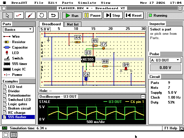
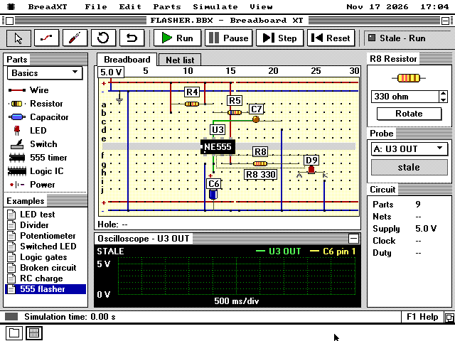
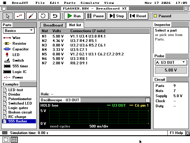
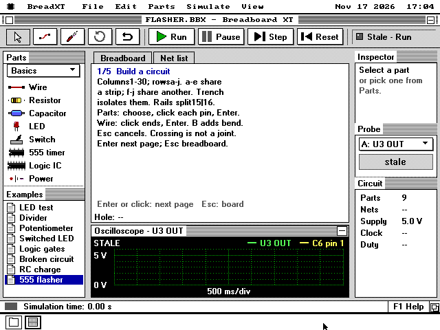
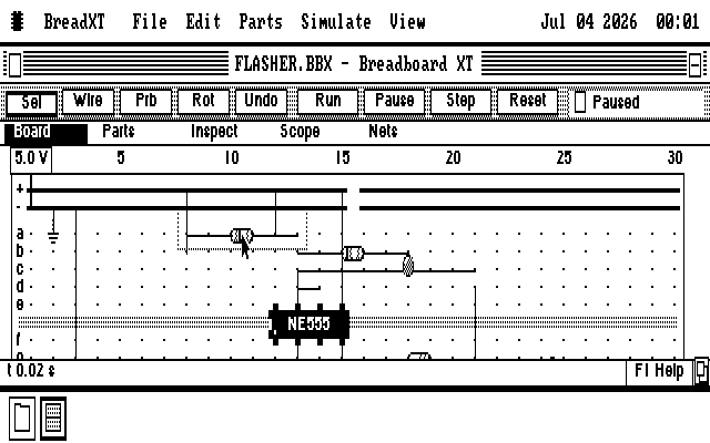
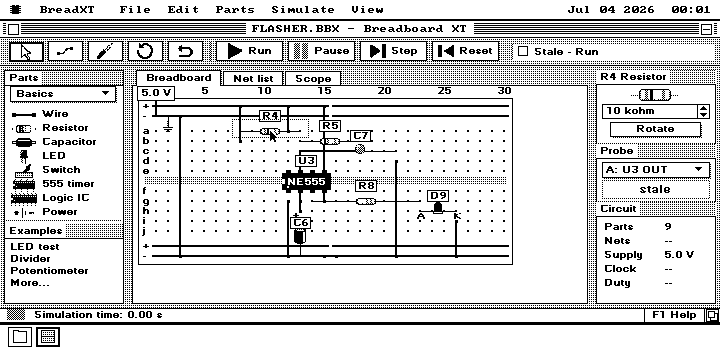
03 / How it works
How it works
When you press Run, Breadboard XT first finds the nets: the groups of holes the strips and wires connect. Each net gets one voltage. Each step of time, the program writes one equation per net saying that the current flowing into it equals the current flowing out, and solves them all together. A capacitor's charge carries over from one step to the next, which is how the timer's capacitor rises and falls. The default step is one millisecond, and Simulate > Larger timestep makes it longer.
The 8088 has no instructions for fractions, and the IBM PC usually has no maths chip. So the arithmetic is done in software, and it checks its own work: a result it cannot trust is reported as a failure, never shown as a wrong number.
The logic chips use four states rather than two: low, high, unknown and floating. A gate whose input is not connected says so instead of guessing. The 555 is modelled pin by pin, so it behaves the way its datasheet describes when its threshold and trigger pins are wired to a capacitor.
The workbench is drawn off-screen in strips and copied to the screen, and only the parts of it that changed are drawn again. On MartyPC's emulated 4.77 MHz IBM PC, opening the 555 flasher draws the whole window in 1.43 seconds on CGA, 2.95 on Hercules and 6.22 on VGA. VGA takes longest because each of its pixels is spread over four separate memory planes.
A saved circuit is a small file, at most 3,120 bytes, with the extension .BBX. Double-clicking one opens it in Breadboard XT.
04 / What it does not do
What it does not do
It is slow on the original PC. On a 4.77 MHz IBM PC, with a 4 ms step, the 555 flasher advances about 2.5 milliseconds of circuit time every second, so one flash of the LED takes minutes. The program stays usable while it calculates. A faster PC, or an emulator like the one the clip above was recorded in, runs it much faster.
It is a teaching tool, not a design tool. The models are simplified. The 555 is an ideal one, and there are no transistors, diodes other than LEDs, inductors or mains-powered parts. There is one power supply, between 4.5 and 6 volts, and a second one is reported as an error.
A board has limits. Up to 64 parts, 128 wires and 64 connected groups of holes. Wires that cross on the screen are not connected; only holes are.
05 / Run Breadboard XT
Run Breadboard XT
Get the Breadboard XT disk from the release zip, in
PROGRAMS/BREADXT/, in the size your drive takes. It is also on the everything disk sets, on the live USB and CD, and on The Wire.Boot the system disk, put the Breadboard XT disk in drive B and open it.
Double-click
FLASHER.BBX, orBREADXT.O88and then 555 flasher in the Examples list.Press Run, or Space. Press F1 for Help.